Toggle Nav
Select Store EN code is temp removed to debugYour email must be verified before you can log in. A message with a link to complete the verification process has been sent to your email address.
The performance of a stepper motor — both in terms of resolution (or step size), speed, and torque — is influenced by construction details, which at the same time may also affect how the motor can be controlled. As a matter of fact, not all stepper motors have the same internal structure (or construction), as there are different rotor and stator configurations.

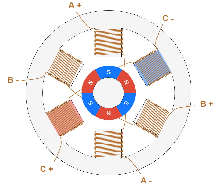
For a stepper motor, there are basically three types of rotors:
Figure 3: Permanent Magnet Stepper Motor
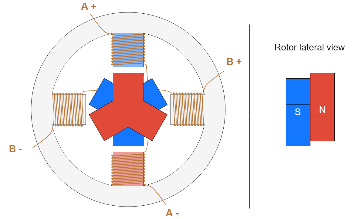
Figure 4: Hybrid Stepper Motor
The stator is the part of the motor responsible for creating the magnetic field with which the rotor is going to align. The main characteristics of the stator circuit include its number of phases and pole pairs, as well as the wire configuration. The number of phases is the number of independent coils, while the number of pole pairs indicates how main pairs of teeth are occupied by each phase. Two-phase stepper motors are the most commonly used, while three-phase and five-phase motors are less common (see Figure 5 and Figure 6).
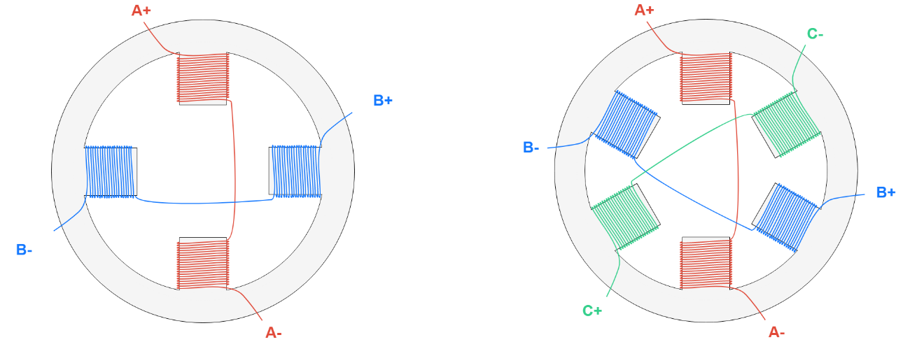
Figure 5: Two-Phase Stator Winding (Left), Three-Phase Stator Winding (Right)
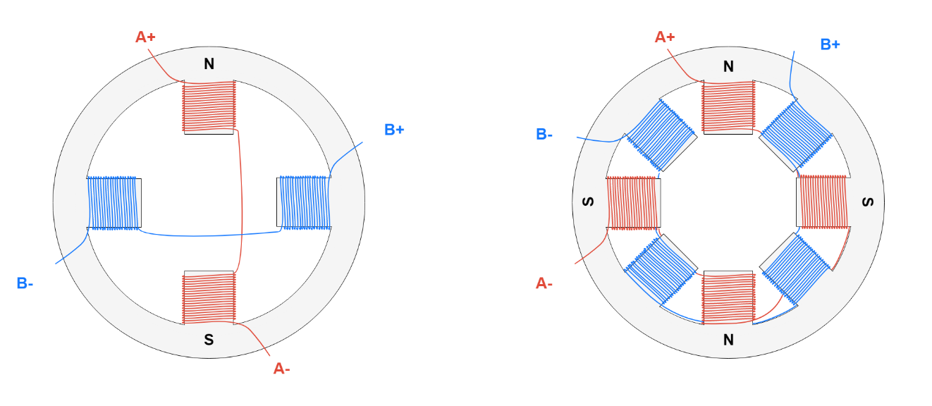
Figure 6: Two-Phase, Single-Pole Pair Stator (Left) and Two-Phase, Dipole Pair Stator (Right). The Letters Show the Magnetic Field Generated when Positive Voltage is Applied between A+ and A-.
We have seen previously that the motor coils need to be energized, in a specific sequence, to generate the magnetic field with which the rotor is going to align. Several devices are used to supply the necessary voltage to the coils, and thus allow the motor to function properly. Starting from the devices that are closer to the motor we have:
Figure 7 shows a simple representation of a stepper motor control scheme. The pre-driver and the transistor bridge may be contained in a single device, called a driver.
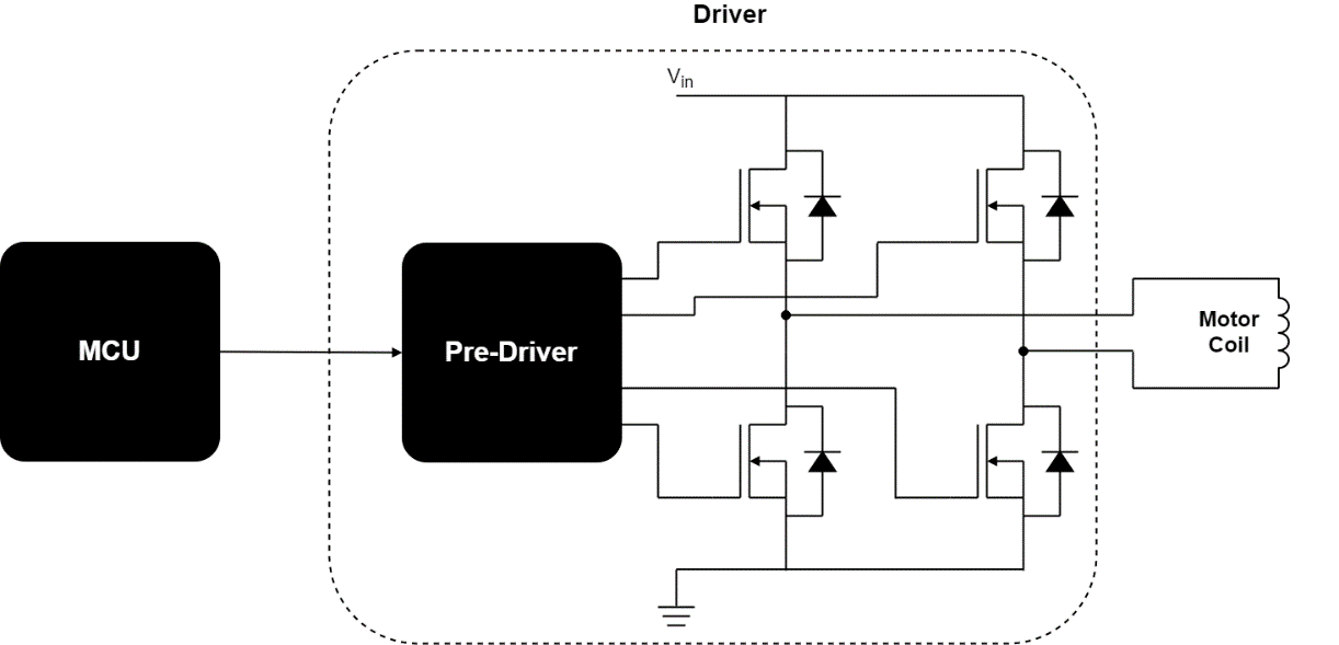
Figure 7: Motor Control Basic Scheme
There are different stepper motor drivers available on the market, which showcase different features for specific applications. The most important charactreristics include the input interface. The most common options are:
Another important feature of a stepper motor driver is if it is only able to control the voltage across the winding, or also the current flowing through it:
Another feature of the motor that also affects control is the arrangement of the stator coils that determine how the current direction is changed. To achieve the motion of the rotor, it is necessary not only to energize the coils, but also to control the direction of the current, which determines the direction of the magnetic field generated by the coil itself (see Figure 8).
In stepper motors, the issue of controlling the current direction is solved with two different approaches.

Figure 8: Direction of the Magnetic Field based on the Direction of the Coil Current
In unipolar stepper motors, one of the leads is connected to the central point of the coil (see Figure 9). This allows to control the direction of the current using relatively simple circuit and components. The central lead (AM ) is connected to the input voltage VIN (see Figure 8 ) . If MOSFET 1 is active, the current flows from AM to A+. If MOSFET 2 is active, current flows from A M to A-, generating a magnetic field in the opposite direction. As pointed out above, this approach allows a simpler driving circuit (only two semiconductors needed), but the drawback is that only half of the copper used in the motor is used at a time, this means that for the same current flowing in the coil, the magnetic field has half the intensity compared if all the copper were used. In addition, these motors are more difficult to construct since more leads have to be available as motor inputs.
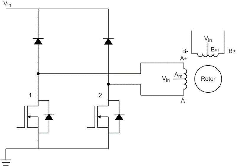
Figure 9: Unipolar Stepper Motor Driving Circuit
In bipolar stepper motors, each coil has only two leads available, and to control the direction it is necessary to use an H-bridge (see Figure 10). As shown in Figure 8, if MOSFETs 1 and 4 are active, the current flows from A+ to A-, while if MOSFETs 2 and 3 are active, current flows from A- to A+, generating a magnetic field in the opposite direction. This solution requires a more complex driving circuit, but allows the motor to achieve the maximum torque for the amount of copper that is used.
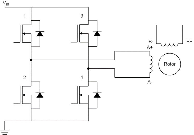
Figure 10: Bipolar Stepper Motor Driving Circuit
With technology progress, the advantages of unipolar are becoming less relevant, and bipolar steppers are currently the most popular.
There are four different driving techniques for a stepper motor:

Figure 11: Wave Mode Steps

Figure 12: Full-Step Mode Steps
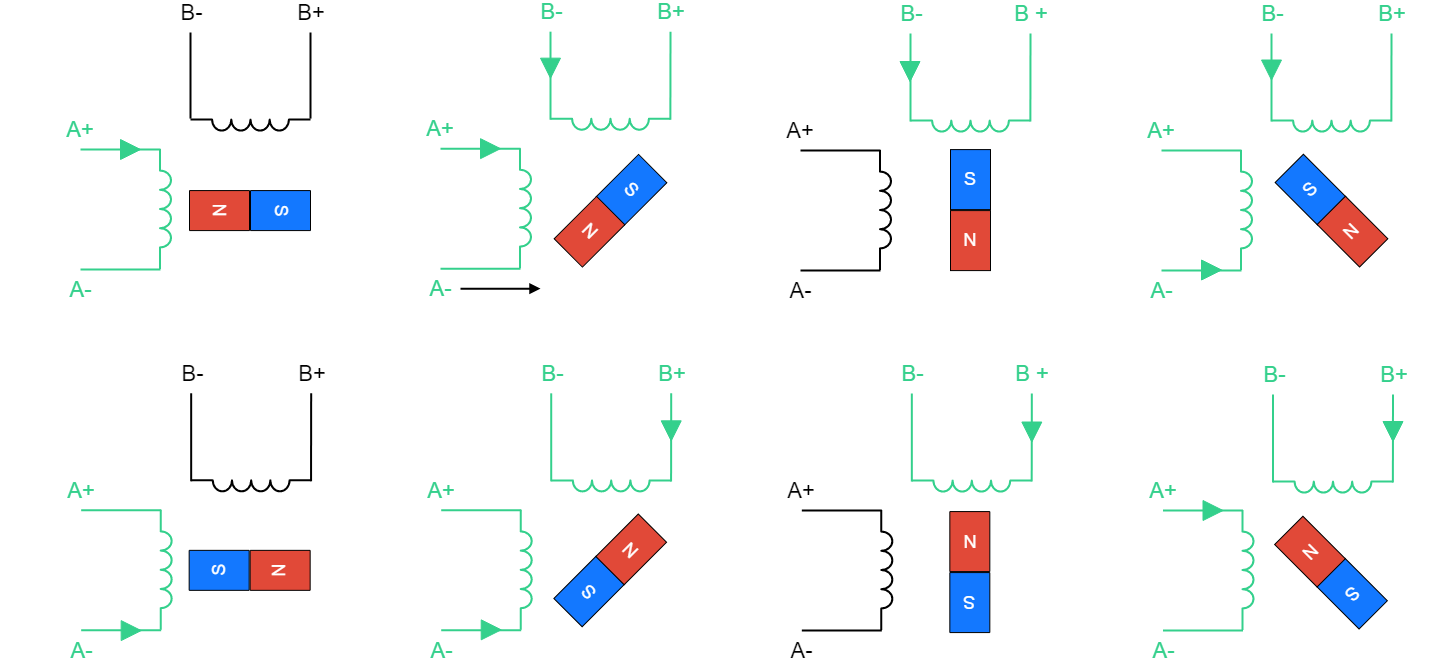
Figure 13: Half-Step Mode Steps

Figure 14: Microstepping
Now that we understand the working principles of the stepper motors, it is useful to summarize their pros and cons compared to other motor types.
To summarize, stepper motors are good when you need an inexpensive, easy-to-control solution and when efficiency and high torque at high speeds are not necessary.
To learn more about how to pick the right type of motor for your project, and the differences between stepper, brushed, and brushless motors click here.
Due to their properties, stepper motors are used in many applications where a simple position control and the ability to hold a position are needed, including:
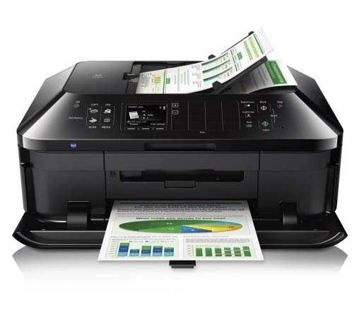
Printers: Printheads, Paper Feed, Scan Bar
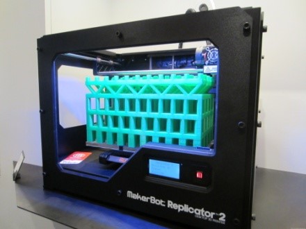
3D Printers: XY Table Drive, Media Drive

Robots: Arms, End Effectors

DSLR Cameras: Aperture/Focus Regulation
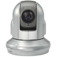
Video Cameras: Pan, Tilt, Zoom, Focus
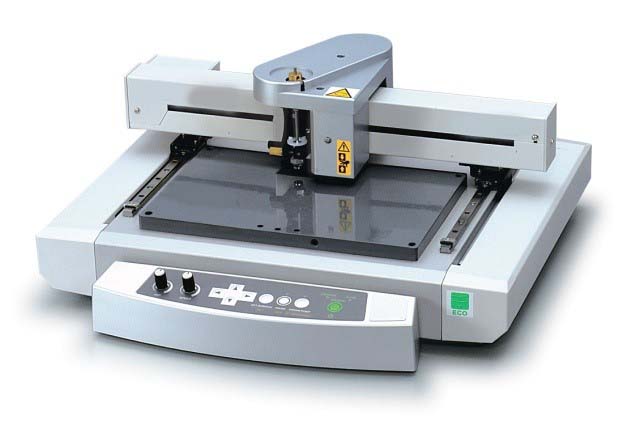
Engraving Machines: XY Table Motion
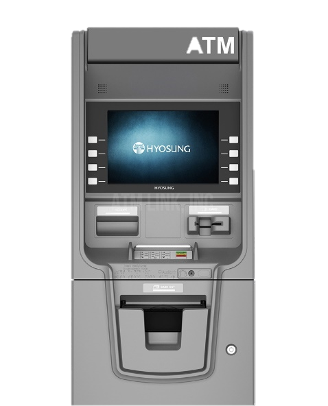
ATM Machines: Bill Movement, Tray Elevators
I am working with a gimbal motor within 3 hall sensor, each hall sensor in angular distance is 120 degree. Can MP6546 correctly work with it?
MOTOR DRIVERS/SENSORS Latest activity 2 days ago 4 Comments Maximum PWM Frequency for MP6541AHi, In the datasheet I can only see frequencies up to 200kHz considered for MP6541A - specifically in the operation current vs PWM frequency plot. Is.